Executive summary:
With the introduction of nG (n>=5), mobile networks and the equipment that runs them must become more software-driven, virtualized, flexible, intelligent and energy efficient. In the RAN domain, vendor agnostic commercial off-the-shelf (COTS) hardware has the potential to enable innovation across a range of software ecosystems. Inline with it, there are potential for an openness within the RAN ecosystems and its is the key enabler of CSP’s OPEX and CAPEX profile.
The blog is the continuation of the 5G series, we will be covering RAN domain only as a part of 5G series 2nd part. We are going to cover concept of the RAN domain in traditional network, virtualized RAN concept, its pros & cons and moreover the concept of open RAN, its association with openness, limitation in the context of capex/opex profile and technical viewpoint.
Different virtualized RAN deployment model in the boundary of 5G RAN, shared with LTE or impact assessment with 2G/3G and cost-effectiveness of the deployment model.
vRan(Virtualized Ran) Philosophy:
In simple terms, a Radio Access Network (RAN) is part of telecommunication access network, communicates end user cell phone/device over radio frequency and connects internally to the CSP core network and further connect to internet/establish communication with another user device/cell.
Traditional Ran architecture
- In this approach, we have antenna, RHE (radio head equipment) and BBU (base band unit)
- In specialized hardware with Proprietary software resulting high capex and opex value.
- CSP(s) has been deploying since 2G era without having a choice.
- It also implies multi-vendor deployment provides high opex value in the context of OSS and NOC management that has cascade effect in BSS area as well.
To make RAN deployment cost-effective what are the areas that need to look at – following are the layers that can be part of disaggregation.
- Ran Radio Hardware
- Compute area
- Management Plane
- Control Plane
In 3gpp Release 15 identifies 3 distinct gNodeB functions:
- Radio Unit (RU)
- Distributed Unit (DU)
- Centralized Unit (CU)
There are several ways to configure these 3 components, and deciding which configuration is best depends on each individual network.
Before jumping into CU DU and RU split – we need to understand LTE and 5G NR protocol stack and the concept of user plane, control plane that was introduced by 3gpp to work as independent unit can be used for effective signal and data Bearer management and tis scaling parameters.
Radio Protocol Stack Architecture
NR Radio Protocol Stack Architecture is almost same as LTE Radio Protocol Stack architecture of the radio protocol stack defines in 3GPP 38.300.
As in NR radio protocol stack has two different stack depending on the type of data that is processed by the stack.
If the data is Signalling message, it goes through the C-plane stack If the data is data message, it goes through the U-Plane stack.
Both U-Plane and C-Plane is made up of a common structure:
PHY <-> MAC <-> RLC <-> PDCP
In case of U-Plane, a layer called SDAP is sitting at the top of the radio stack and the SDP is connected to UPF (User Plane Function).
In case of C-Plane, the two layers RRC and NAS are sitting at the top of the stack. NAS layer gets connected to AMF (Access and Mobility Management Function).
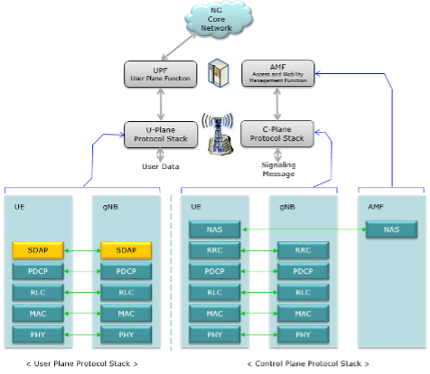
NR support carrier aggregation from the beginning, data for each carrier is processed separately for each carrier in SDAP, PDCP, RLC and multiplexed/scheduled in the common MAC layer. This is also same as LTE Rel 10 or higher.
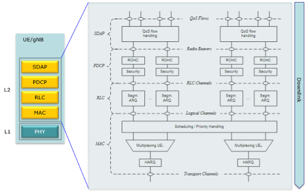
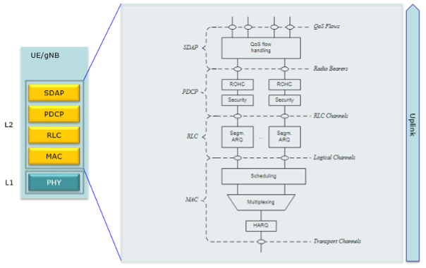
Following is L2 structure of NR U-Plane Uplink radio protocol. Basic structure is same as downlink structure except that Uplink does not support carrier aggregation.
Architecture RoadMap: Traditional Ran -Virtual Ran – Open Ran
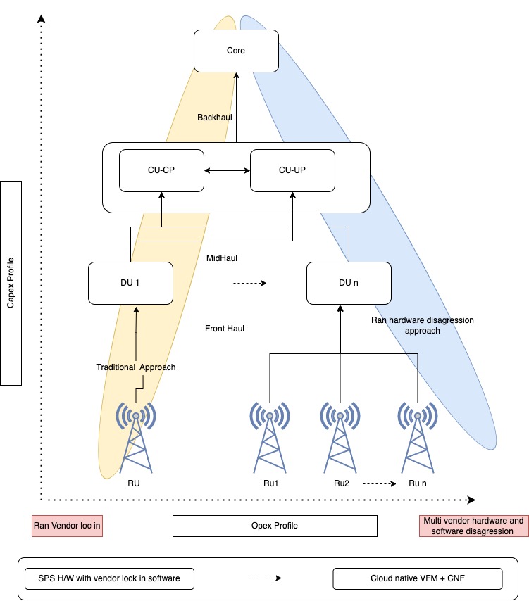
There are several deployment options that CSP can choose from based on the following.
- Protocol split.
- RAN Hardware software disaggregation.
- Protocol split and RAN Hardware software disaggregation.
- Protocol split, RAN Hardware software disaggregation and proactive service/resource assurance including optimization feed.
Please note, RU – BBU – Core (BBU is on commercial deployment mode) is still a traditional approach option.
Major Pain points of Radio hardware disaggregation:
- Cloudification of DU with real time processing and high computation platform
- Introduction of Fronthaul, Midhaul and path loss
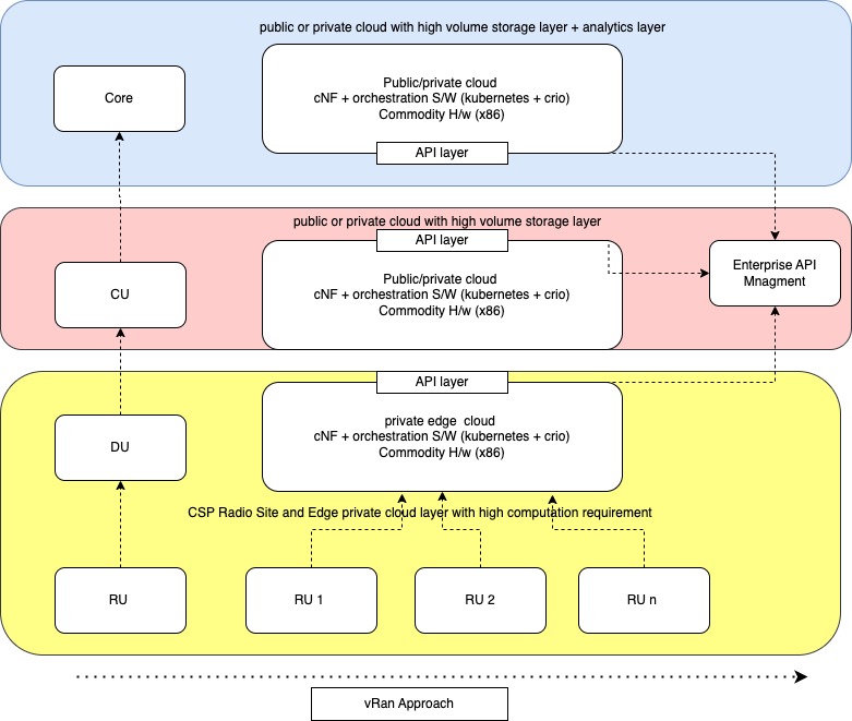
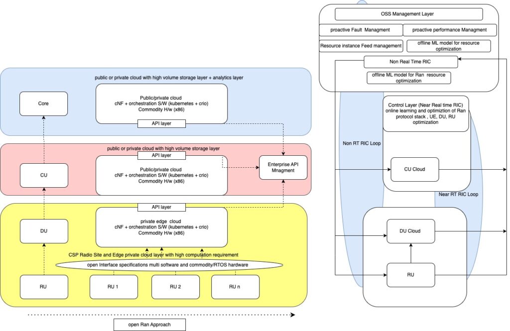
To BE Reference Architecture vRan -> Open Ran
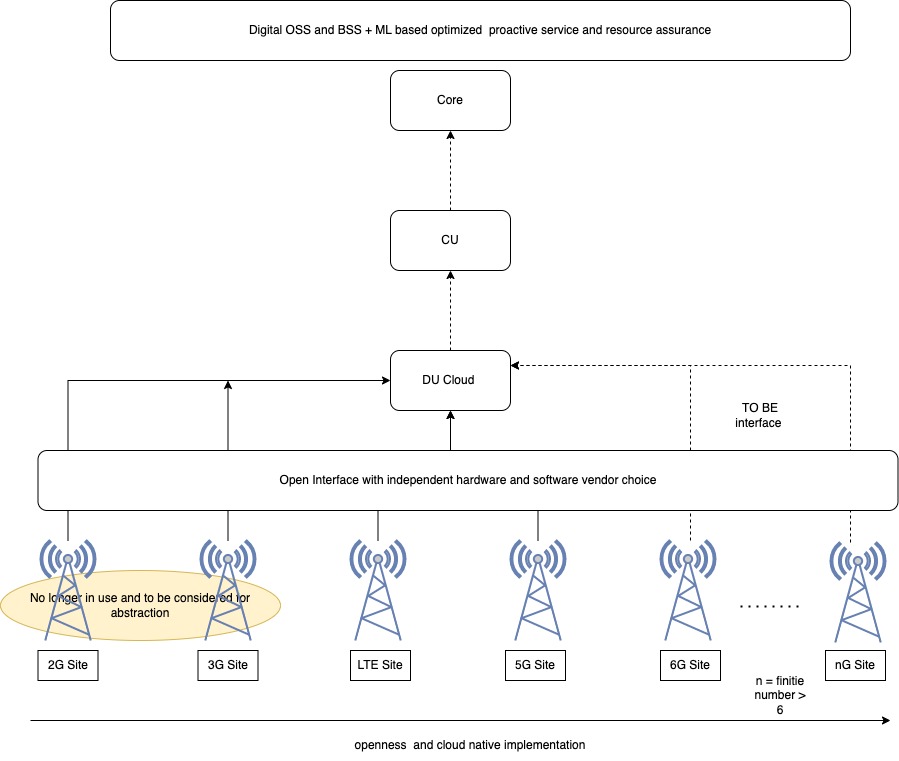
Open Digital Architecture: Foundation view O/BSS
Conclusion:
We have covered basic building block of RAN architecture, traditional RAN approach, its pain points, 5G and cloud native architecture its OPEX/CAPEX profile, pain points moreover OpenRAN concept and how it associated with vRAN , but openRAN doesn’t mean it is open solution always. It provides flexibility to decouple RAN hardware software with open eCRPI interface, it’s goal towards openness and optimization of Radio parameters with the lights of machine learning. Hence it is the foundation for self-optimized digital open O/BSS eco system.
We will cover CRPI/ECRPI interface and protocol split in detail in the upcoming blog.
Happy Learning!