Introduction:
SA3 group within 3GPP is currently responsible for security in the 5G System including the 3GPP enhancements for IoT and vertical industries. Furthermore, since the introduction of the 5G System, SA3 has been developing the security requirements and test cases for network equipment implementing any of the new 5G Network Functions.
Following are the latest update that covers Radio access network and Industrial IOT security threat models and associated risk details as follows
- Ran security: user plane integrity protection – Integrity protection is a security feature that allows a receiver to determine that the received messages were not tampered with by an attacker
- Ran auxiliary security Secure Industrial IOT communication with 5G systems – covering Ultra-Reliable and Low Latency (URLLC)
- Ran Security: False base station protection
- Ran security: Mobile proximity service.
Before we go ahead and explain each of the above areas, let’s simplify with why and what space.
And last but not the least – we will see overall architecture impacts of above security areas and if any overkill processes need to be carried out by vendor or CSP for above implementations.
Ran security: user plane integrity Protection
Quick Recap: User plane in 5G
Schematically, the 5G system uses the same elements as the previous generations: a User Equipment (UE), itself composed of a Mobile Station and a USIM, the Radio Access Network (NG-RAN) and the Core Network (5GC), as shown in the figure below.
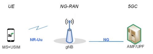
Figure 1: overview of the 5GS
The main entity of the NG-RAN is the gNB, where “g” stands for “5G” and “NB” for “Node B”, which is the name inherited from 3G onwards to refer to the radio transmitter. The radio interface is named “NR-Uu” for similar reasons, although with divergences: here, “5G” is indicated by “NR” (for “New Radio”) and Uu is also a name inherited from previous generations. The gNB may be further split into a gNB-Central Unit (gNB-CU) and one or more gNB- Distributed Unit(s) (gNB-DU), linked by the F1 interface.
The 5GC is here schematically represented by the AMF/UPF entity: the User Plane Function (UPF), handling the user data and, in the signalling plane, the Access and Mobility management Function (AMF) that accesses the UE and the (R)AN.
.
What is Integrity protection?
Integrity protection is a security feature that allows a receiver to determine that the received messages were not tampered with by an attacker. While integrity protection has been available since 3G to the messages used for the management of resources called Control Plane messages, it was only in 5G Release 15 that the messages used for carrying user traffic called User Plane messages were enhanced with integrity protection as well.
Key Threat points and Risk mitigation approaches
UP integrity activation in EPS
Secure negotiation of integrity protection support in EPS
UE support of UP IP at the full uplink data rate
Integrity protection capability imbalance in enodeB connected to 5GC
Optionality of integrity protection in UP DRB with 5GC
UE connected to 5GC indicating support of UP IP over eUTRA
Ensuring UP IP is enforced at interworking
HPLMN Control of UP IP usage in EPC
Solution
The UE identifies/decides to send particular IP packet (UP signalling messages) over the established PDU session, based on at least one of the following Traffic Filtering information:
– application layer protocol (for example: DNS).
– Transport layer port numbers.
– Destination IP address and/or source IP address.
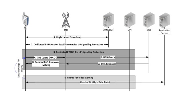
Figure:2 Dedicated PDU for UP Signalling message IP
This solution enables the integrity protection of the UP signalling messages, when the integrity protection of a PDU session is not activated due to UE capability limitations, using a dedicated integrity protection enabled PDU session. With the solution the key issue #5 (Optionality of integrity protection in UP DRB) is addressed.
The impact to the UE and the AMF is to have a new DNN configuration and it can be done as part of URSP procedure or other mechanisms, for the establishment of a dedicated integrity protection enabled PDU session, to protect the sensitive message exchanges (for example, DNS exchanges).
This solution is applicable for resource constraint Rel-15 and Rel-16 UEs, which can support integrity protection of sensitive application layer signalling messages (like DNS messages) only and does not support integrity protection of other non-signalling UP traffic.
Following are the identified threats defined in 3GPP TR 33.853
Introducing user plane integrity protection (UP IP) to EPS means that there will be a need to deal with legacy (CN and RAN) nodes that do not support UP IP and upgraded nodes that do support UP IP. As described in Key Issue #7, there is a need to ensure that a legacy RAN node does not configure a bearer that requires UP IP as it cannot support UP IP. While the key issue focuses on interworking, it is similarly true during mobility in EPS.
This solution provides a method of ensuring that the bearer that requires UP IP is not handed over from a ng-RAN node to an eNB that does not support UP IP. The solution works by the target eNB providing an indication that it supports UP IP as part of its response to a request for a handover initiated by an ng-RAN node connected to 5GS. If the source ng-RAN node gets no indication that the target eNB supports UP IP, then the source ng-RAN node does not proceed with a handover procedure for the UE that has bearers that require UP IP.
Whether the UP IP support indication is signalled in the target to source transparent container or on a hop by hop basis will depend on the rest of the solution, e.g. it could be necessary to know that the intervening nodes on the handover signalling path support UP IP in EPS but this can be already be known due to other aspects of a chosen solution.
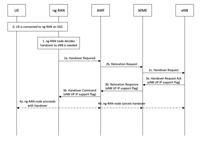
Figure 3: Restricting handovers to RAN nodes that don’t support UP IP
The steps proceed as follows:
UE is connected to an ng-RAN node
ng-RAN node decides a handover to an eNB is needed
ng-RAN node initiates the handover preparation (via AMF and MME) to the eNB
eNB responds to handover preparation (via MME and AMF) and if it supports UP IP the eNB includes an indication of its support for UP IP. The indication can be carried hop by hop or end to end manner.
Network’s UPIP policy
The preference or requirement of the network pertaining to the activation of UPIP is contained in the UPIP policy. The policy can take one of the following values:
- Required. It is mandatory for the RAN (eNB in Option 1 and gNB in Option 3) to activate UPIP. If the RAN cannot activate UPIP, it must not establish DRBs.
- Preferred. It is recommended (but optional) for the RAN to activate UPIP. If the RAN cannot activate UPIP, it is still allowed to establish DRBs.
- Not needed. It is forbidden for the RAN to activate UPIP.
5G Deployment Architecture Impact
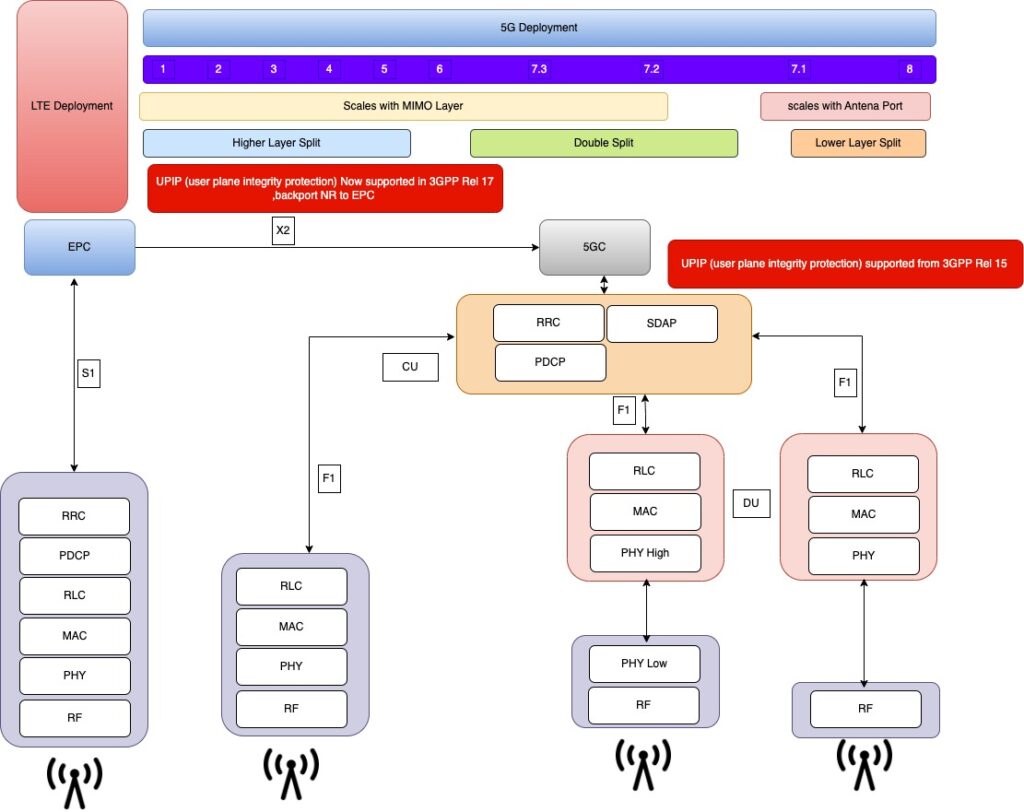
Fig 4: 5G deployment Architecture with security features UPIP
Abbreviations
AN Access Network
AS Access Stratum
CP Control Plane
DRB IP Data Radio Bearer Integrity Protection
EN-DC eUTRA-NR Dual Connectivity
EPS Evolved Packet System
eUTRA evolved Universal Terrestrial Radio Access
IP Integrity Protection
NR New Radio (5G)
RAT Radio Access Technology
SMC Security Mode Command
UE User Equipment
UP User Plane
UP IP User Plane Integrity Protection
Conclusion:
We have discussed details 3GPP Phase 2 Security updates overview and covered UPIP and backward compatibility for 4G defined in 3GPP
next couple blogs we will cover
Industrial IOT and 5G security
Ran Security: False base station protection
Ran security: Mobile proximity service.
Happy Learning!