Executive Summary
Functional split is not a new concept in RAN domain, when we moved from 2G to 3G world, CSP had already implemented functional split abstracting in the following way.
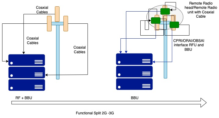
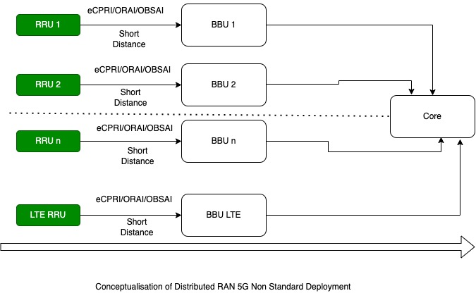
Fig 1
- Antenna Radio Unit and BBU 2G deployment (antenna integrated with coaxial able to RFU and BBU
- Antenna Remote Radio/Remote Radio Head Unit (RF unit) and BBU unit
- RFU, Fronthaul and BBU pool/BBU hotel
- RFU, Fronthaul and vBBU
- RFU, Fronthaul, Midhaul, vCU,backhaul and vCore
Fronthual Approach and interface
For simplicity let’s consider we haven’t split BBU to DU and CU, and what’s the interface RFU communicates with?
The answer is the following interface.
- CRPI interface, digitized and serialized base station interface.
- OBSAI interface – Open Base Station Architecture Initiative
- ORI interface – Open Radio Interface
OBSAI Approach:
The organization was tasked with standardizing the architecture of wireless base stations, internal interfaces, control modules, transmission modes, baseband band and radio frequencies. However, the possibilities of OBSAI were limited to the fact that standards were developed in the mainstream of base stations of only one manufacturer – Nokia.
CPRI Approach
According to the CPRI standards, the base station consists of two parts: a Baseband Unit (BBU), or a Radio Equipment Control (REC) unit, and a Radio Frequency Unit (RRU) or radio access equipment, RE. The main distinguishing feature of CPRI interfaces is the separation between the base frequency band and the radio frequency band. Small size, ease of installation and a variety of functions with low power consumption allows you to use the BBU on existing objects and support the extension in the cascade connection mode. Due to its small size and weight, the RRU is easily mounted on a pole or wall near the antenna, maximizing its radio coverage. CPRI standardizes interfaces between the BBU and RRU, ensuring compatibility of equipment from different manufacturers.
ORI Approach
The ORI interface is built on top of the interface already defined by the CPRI (Common Public Radio Interface) group. However, options are removed and functions are added with the objective of making the interface fully interoperable. • ORI Release 1 provides support for UMTS, LTE and LTE-Advanced technologies.
• ORI Release 2 adds support for multi-hop topologies and RRU chaining, as well as 9.83 Gbit/s line bit rate, and is based upon CPRI version 4.2.
• ORI Release 3 extends support to GSM technology and is based on CPRI version 5.0. • ORI Release 4, published in October 2014, is based on CPRI version 6.0. Release 4 adds IQ data compression for LTE and supports a line bit rate up to 10.14 Gbit/s
eCRPI Approach:
eCPRI is designed to handle such diverse fronthaul types. eCPRI supports service points for:
- User plane traffic
- Synchronization
- Control and Management
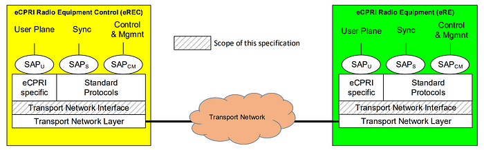
These service points are handled by the eCPRI protocol stack over IP/Ethernet.
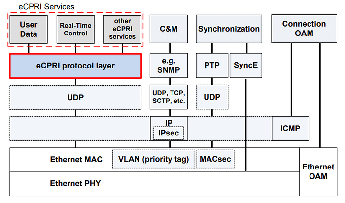
Advantages of eCPRI
- Ten-fold reduction of required bandwidth
- Required bandwidth can scale according to the to the user plane traffic
- Ethernet can carry eCPRI traffic and other traffic simultaneously, in the same switched network
- A single Ethernet network can simultaneously carry eCPRI traffic from several system vendors.
- Ethernet-OAM may be used for operation, administration, maintenance, provisioning, and troubleshooting of the network
- The new interface is a real-time traffic interface enabling use of sophisticated coordination algorithms guaranteeing best possible radio performance
- The interface is future proof allowing new feature introductions by SW updates in the radio network
- Jitter and latency will be reduced for high priority traffic using Time Sensitive Networking standard IEEE 802.1CM. The 802.1CM supports preemption of a low priority packet to schedule a high priority delay and jitter sensitive transmission.
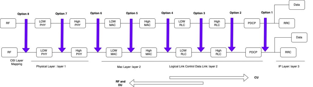
Ran Deployment Options
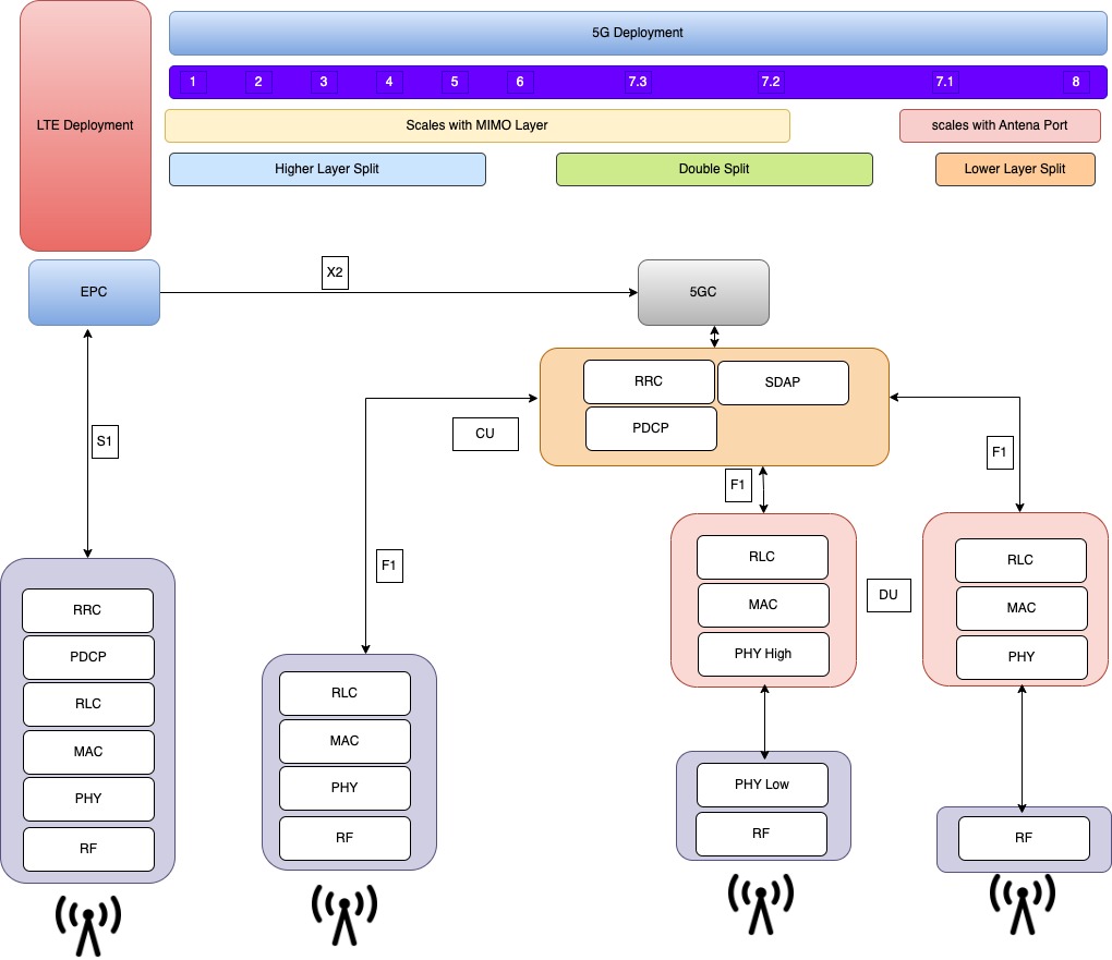
Functional Split RU-DU-CU
Midhaul and Backhaul Deployment
Ideal Deployment LTE and 5G Macro and small cell
Missing link
We have discussed different deployment option(s) in the following categories
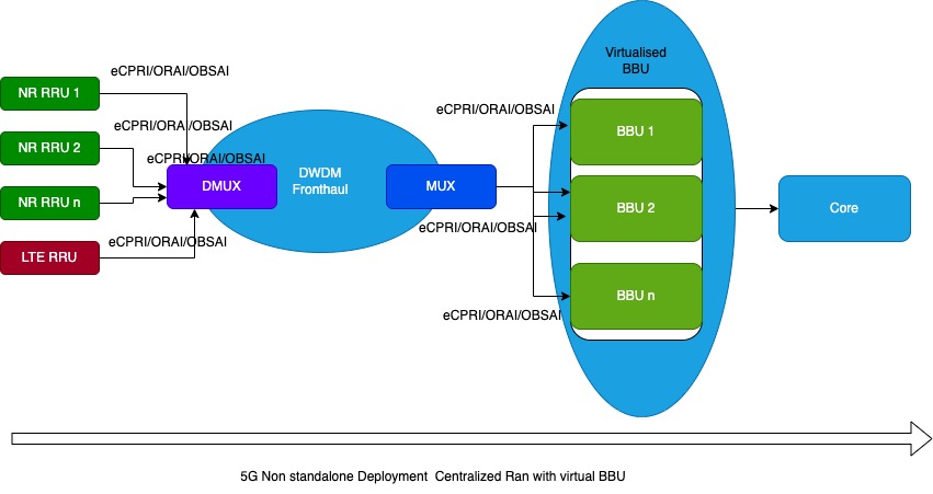
- Fornthaul – in the cost of new introduction of DWDM as transport network but can be qualified for virtualRan
- Distributed Ran , in the cost of vendor specific BBU
- 3GPP reference architecture – and functional split
- Ideal deployment option with combination of LTE,5G Macro and small cells
Question is : will it be sufficient to deploy 5G network without adding more cost to business, what we are waiting for ?
The answer is not virtualization only, but in the following way
- Introduction of Control Loop that provides feedback of operation and usage to the planning system/planning team
- Introduction of Continuous feedback in the form of current instance and predictive modelling and improve model accuracy each day.
- Now Virtualization can unlock software Hardware tight coupling unless we have optimization and feedback in place
- Introduction of Business capabilities as platform for products – minimize the each product architecture and bring service based SLA to into the platform scope.
Conclusion
The functional split in other words determine the cost effectiveness deployment scenario for CSP to minimize the TCO for overall RAN domain and might be fall into the following categories.
- Cost effective Deployment Model
- Network optimization
- 1 and 2 both
But, here is the trade off, when we say we are deploying traditional approach i.e. 8:1 split, we are hardware software locked in and proprietary software/hardware can be optimized based only in a reactive way, hence it gives good reason for go ahead with software driven approach and performance optimization can be also be part of load and cell co-ordination point of view.
Happy Learning ! we will cover 5G security including platform, SBA in the next blog.